Andrew Cooke | Contents | RSS | Previous
Welcome to my blog, which was once a mailing list of the same name and is still generated by mail. Please reply via the "comment" links.
Always interested in offers/projects/new ideas. Eclectic experience in fields like: numerical computing; Python web; Java enterprise; functional languages; GPGPU; SQL databases; etc. Based in Santiago, Chile; telecommute worldwide. CV; email.
Choochoo Training Diary
Simple, Fast Integer-Based Compression Of Digital Audio Signals
Using __not_in_flash_func with templates (pico SDK)
Raspberry Pico 2040 ADC - Take Two
Testing Raspberry Pico 2040 ADC Corrections
DNL/INL and Raspberry Pico 2040
Fast integer <-> float conversion
Hello World on Music Thing Modular (from Linux)
Reddit Comment on Fascism + Trump
[Computing] Efficient queries with grouping in Postgres
[Computing] Automatic Wake (Linux)
[Computing] AWS CDK Aspects in Go
[Computing, Horror] Biological Chips
[Physics] Quantum Transitions are not Instantaneous
Applebaum - Twilight of Democracy
You can Masquerade in Firewalld
Update - Garmin Express / Connect
© 2006-2025 Andrew Cooke (site) / post authors (content).
From: andrew cooke <andrew@...>
Date: Sat, 4 Apr 2026 18:28:14 -0300
This is for the Moulinex bread machine.  It makes a light, "french"
loaf.  Writing it down here mainly for my own reference.

* Heat water to 40C

* Add 300ml warm water to bread tank

* Add 2tbsp olive oil (gives good taste) and 2tsp salt to tank.

* Mix 2tsp dried yeast and 2tsp sugar with a little water (tbsp or so)
  in a jug and leave to bubble a little while sieving flour.

* Sieve 500g of white bread flour into a bowl and then spoon into
  tank.

* Make a depression in the flour and pour in the yeast mix.

* Add some more of the warm water to the jug and start the machine
  (program 6, 750g, dark).

* During the initial mixing, add water from the jug until it's as wet
  as you can get without being too wet.  I don't know how to describe
  this, and getting the right amount is critical.  Basically, when all
  the flour is incorporated it should be a single mass that forms a
  ball, but wet enough that at the bottom of the pan there's a little
  residue that doesn't get mixed in completely.  It's definitiely
  wetter than cooking by hand.  Also, the ball is has a "head" that
  sticks in one corner of the tank...  As I said, I am writing this
  mainly to remind myself.

* Once you have the right consistency, close the lid and don't peek
  until done.

Andrew
Permalink | Comment on this post
For comments, see relevant pages (permalinks).
From: andrew cooke <andrew@...>
Date: Mon, 8 Dec 2025 13:34:10 -0300
i'm writing this note partly as a diary, and partly as a guide for
gringos thinking about cycling from santiago to valparaíso when the
roads are closed for the pilgrimage.  i am likely going to describe
things that are really obvious to locals, but might not be as clear to
foreigners.

it is based on my experience riding the route (for the first time) on
december 7, 2025.  here's my strava record -
https://www.strava.com/activities/16685380450

the main highway was closed from 4pm sunday till 8am monday (so
really, just overnight for cycling), but a small section near lo
vásquez was closed all day monday which doubled travel time returning
monday by bus.

leaving home at 3pm i made my way to the service station at
https://maps.app.goo.gl/2wZ5KFT6ioN8dHiU8 via the alameda ciclovía and
av gral oscar bonilla.  route 68 is closed from the intersection with
vespucio just east of there.

i arrived maybe 15min after 4 and the road was already closed to
traffic, although there were still people arranging cones, police on
motorbikes telling people to move over, etc.  so it was working but not
"established".

still, there were a fair number of people - enough to be able to catch
a passing peloton, but not enough to slow you down.  if your main
emphasis is on the ride (i will discuss the social aspect below) then
this is a good time to start, i think - i arrived in valpo at sunset.

riding to the first tunnel (lo prado) was an easy uphill, but the
headwind was pretty fierce.  i followed a group, that helped provide
shelter, but i was a little cautious about entering the peloton, not
knowing the riders (i should say that i didn't see a single accident
all night).

more generally, you could divide cyclists into 3 rough groups. the
fast guys (almost all men, carbon frames, deep aero wheels etc etc),
the sports cyclists (mainly road bikes, lycra, more women, a few flat
bars), and the casuals (mainly mtb).  i was passed by, and would
re-pass, the same the riders again and again, as we stopped to eat,
took climbs slowly, etc. in retrospect i should have chatted more with
people.

my original plan was to cycle 50km or so (maybe to curacaví) and then
return. but the returning lane still had traffic at that point, i was
feeling pretty good, there was a big climb to return to the tunnel,
and i had somewhere to stay in valpo, so i decided to push on.

in fact, it was not a simple descent to the coast, as i had hoped (see
strava link for profile).  there were a couple of long, moderately
steep climbs before the second tunnel, and then some smaller climbs
after, before the final step descent into valpo.  the total distance
was 124km (from providencia) which was my longest ride this year
(just) and i should have paced myself better.

there were a lot of small stalls on the route, selling everything from
bottled water to completos, so you could do the ride without taking
food and drink (if you had cash), but i managed perfectly on two
bidons, two bars of manjar, and two pouches of fruit purée (the kind
made for kids' lunches) - my usual for this length ride.

i should mention temperature.  it was actually lower then expected, and
with the wind was comfortable in a thin, long sleeved top - i had been
preparing for a hotter ride (changed to normal sized bidon just as i
went out the door).  but still it was warm at the start, and cool near
the sea. i could imagine a hotter start and cooler finish would
require adding an extra layer as well as more water (maybe start in
short sleeved and put long sleeved over the top later; no need for
thicker fabric).

lo vásquez was a surprise.  the right hand lane - where everyone had
been riding - was a mass of food stalls, extending maybe 1km along the
road.  i switched to the left lane to continue to valpo, and passed
rows of buses, trailers, vans, all to carry people back to santiago (i
had seen some of these advertise on instagram the weeks before - i
didn't see anyone selling there and suspect they were fully booked).

looking at instagram the next day (as i write this), it's clear that
there is another, very different way to experience this route, leaving
later, in the dark.  my impression is that there are many more people
then, with a larger proportion of what i described as "casual" riders
above.  it looks like it would be much more difficult to keep a decent
speed, but that the environment is a lot more like a party.

and there are also the randoneurs - i started to see groups of people
riding the return after leaving the second tunnel.  this would imply
much of the ride in the dark (and with the big climb before lo prado,
but with the wind on your back).

if you want to ride something like my original plan - a limited ride
out to experience the closed road and tunnel, and then a return - i
think it would be better to leave later then i did.  doing this would
let you experience the party vibe and return when other cyclists were
also returning.  even so, i worry some people will use the left lane on
the way out when there are many riders, with possible accidents.

on the steep descent into valpo i was the only person going in my
direction (most people stop at lo vásquez, and i suspect many that
continue will go to viña).  the road was closed all the way until the
top of av argentina!

i was lucky enough to have access to a flat (appt) in valpo, so i
arrived, ate, and slept.  next day i left my bike there and returned by
bus (a longer, but very scenic route).


would i do it again?  it might be interesting to ride slower, later at
night, stopping to eat, chatting to people.  as a long ride, it's a
pleasure riding on well maintained (generally) tarmac, but i don't
know if this outweighs the inconvenience of having to get my bike back
at some point, or the risk of booking transport.  el toyo and
farellones are both more attractive routes, and (usually) the wind is
against you for only half the ride.  maybe i would do it again if i get
fit enough to ride the return too?  but i am getting old...

andrew
From: andrew cooke <andrew@...>
Date: Thu, 2 Oct 2025 18:13:39 -0300
[Maybe this is already known, but I failed to turn up anything with
Google and am pretty pleased with what I dreamt on my own.]
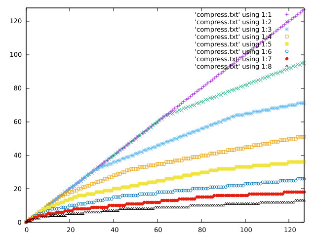
I'm writing software to generate audio signals with an 8 bit DAC and a
relatively weak CPU. I wanted to add a compressor to the audio chain,
but my initial attempts used slow floating point arithmentic. Then I
came up with this:
def compress(n, depth):
for bit = 7-depth to 7:
thresh = 1 << bit
if n > thresh: n = thresh + ((n - thresh) >> 1)
return n
Basically: "divide by 2 above some knee" plus "iterate that for
increasingly large knees". Where depth above selects the degree of
compression required.
In my experience it works pretty damn well.
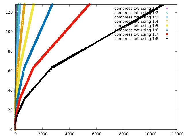
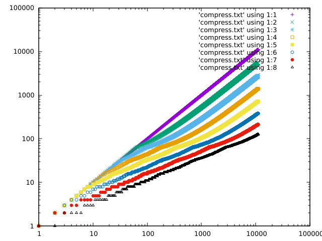
Some plots of the response curve:
https://acooke.org/img/compress-1.png
https://acooke.org/img/compress-2.png
https://acooke.org/img/compress-3.png
Andrew
From: andrew cooke <andrew@...>
Date: Thu, 24 Jul 2025 20:12:08 -0400
An obscure fix that maybe google will pick up and pass on to help out
a poor lost soul...

If you're using __not_in_flash_func with multi argument templates then
why the hell are you using templates in an embedded system?  Lol.  But
some of us enjoy a challenge so...

   template<uint A, uint B> void __not_in_flash_func(Class<A, B>func(int p))() {
     ...
   }

does not work.  It does not work because the comma between A and B
implies two arguments to the macro.

Google AI suggests an extra set of parens:

   template<uint A, uint B> void __not_in_flash_func((Class<A, B>func(int p)))() {
     ...
   }

which gets past the preprocessor, but breaks the linker (where the
comma matters again).

What seems to work (ugly, but you probably don't need it much) is:

   template<uint A, uint B> void __attribute__((section(".time_critical." "my-class-func")))
   Class<A, B>func(int p)() {
     ...
   }

(note all the parens, weird "."s, and lack of comma).

The "my-class-func" defines a group for deletion which should probably
be unique (the macro __not_in_flash_func just uses the argument) - you
should maybe care about template args, but if you're only
instantiating the template in one way (or maybe I am weird) then
that's not an issue.

Good luck!
Andrew
From: andrew cooke <andrew@...>
Date: Wed, 23 Jul 2025 21:58:09 -0400
I've gone down something of a rabbit hole with the corrections for the
Raspberry Pico RP2040 (see the poor DNL data at
https://datasheets.raspberrypi.com/rp2040/rp2040-datasheet.pdf for
context).

My initial steps are described in previous posts here that I won't
link to immediately because they were, in retrospect, very
superficial.  Although they did serve to get me to the point where I
had to really think and try remember details from back when I was a
PhD student.

So I am starting over here.  I will explain the hardware (again), then
the (improved) analysis, the results, and finally make some
suggestions for the ComputerCard library (and explain what I will be
doing in my own code).


Basic Setup
-----------

I'm working with the computer module in the Music Thing Modular
Workshop System.  This exposes the RP2040 through 6 LEDs, a 3 position
switch, and sockets connected to the DACs and ADCs.  There are a few
more knobs and sockets, but it's still a relatively constrained
interface.

To measure / correct the ADC response I decided to (roughly):

 * Generate a known signal - a triangular wave - via one of the DACs.

 * Connect that to an ADC (using a patch cable).

 * Subtract the value sent to the DAC from the value read from the ADC
   to get an error (ideally the two should match).

 * Send the error to the other DAC (for external monitoring).

 * Accumulate errors over time and display the total via the LEDs.

I monitored output from the two DACs on a very simple oscilloscope
(one of those little Korg kits).  This gave me a basic check on the
generated signal and associated errors.

Hopefully the above makes sense.  I'll clarify and expand below, but
one big assumption should already be clear - that I take the DAC to be
perfect.


Corrections
-----------

Rather than just measure the error between DAC and ADC values I
include a correction - the value read from the ADC is passed through
this correction before being compared to the expected value (the value
sent to the DAC the cycle before).  The idea, then, is to adjust the
correction until the error is zero (or, at least, as low as possible).

Actually, I am still not describing the final system.  In practice I
use two connections.  Their exact processing depends on the 3 position
switch:

 * In the "up" position the first correction is applied and the
   associated error sent to the second DAC.

 * In the "middle" position the second correction is applied and the
   associated error sent to the second DAC.

This allows me to compare the two errors on the oscilloscope by
changing the switch position.

Whatever the switch position I continually accumulate the errors (the
exact calculation is described below).  When the switch is in the
third position - "down" - then the sum is displayed on the LEDs.  This
is done in a way that shows both the magnitude (roughly) and sign of
the sum.  The sign of the sum indicates which correction is "best".


Manual Optimisation
-------------------

Given all the above I can now describe the physical process I repeated
time and time again:

 * Compile the code with two closely related corrections

 * Load the code onto the computer

 * Check that the errors look reasonable in the oscilloscope

 * Check the LEDs to see which correction is best

 * Modify one of the corrections in light of the comparison and repeat

In this way, over time, I can iterate to an optimal correction.


Statistical Details
-------------------

How, exactly, do I (or the maths in the code) decide which correction
is best?

For each correction I sum, over many samples, the square of the
difference between the measured and expected value.  Given some
(rather optimistic, but "industry standard") assumptions this sum is
proportional to the probability that the correction is working
correctly (and that the errors are "just noise") (more exactly, this
is the unnormalised log likelihood, assuming constant gaussian
errors).

The value displayed on the LEDs is the difference between the sum for
one correction and the sum for the other (which is why it can be
positive or negative).  The sign indicates which correction is better
and the magnitude shows "how much better" (in practice it is useful as
an indicator for when two corrections are "pretty much as good as each
other").


What Are We Fitting?
--------------------

You might have hoped that was the end of it, but I'm afraid there is
more.

If you naively (as described in my earlier posts) use the correction
from the ComputerCard library, or my own version (which based on that
and the DNL plot in the data sheet), then the errors are actually
dominated by systematic errors.

By systematic errors I mean that there's no guarantee - even without
the DNL glitches - that you get the same number back from the ADC that
you sent out via the DAC.

We can try to correct these changes in value.  To first approximation
we can use two numbers - a zero point and a scale - to model (and so
correct for) linear variations.  Non-linear variations we simply
ignore (while reciting "industry standard" prayers that they are not
important).

So in addition to any parameters in the corrections themselves, we
also have two additional parameters that describe the hardware.


The Corrections
---------------

I considered four corrections (the x and y parameters are adjusted to
optimise the correction, along with the linear correction described
above):

 1 - The null correction - includes only the linear adjustment

 2 - The correction from the ComputerCard library, parameterised as:

       int16_t fix_dnl_cj_px(uint16_t adc, int x) {
	 int16_t bdc = static_cast<int16_t>(adc);
	 uint16_t adc512 = adc + 0x200;
	 if (!(adc512 % 0x01ff)) bdc += x;
	 return bdc + ((adc512>>10) << 3);
       }

 3 - The correction from the ComputerCard library, but with an adjusted
     level for the DNL spikes (0x200 instead of 0x1ff):

       int16_t fix_dnl_cx_px(uint16_t adc, int x) {
	 int16_t bdc = static_cast<int16_t>(adc);
	 uint16_t adc512 = adc + 0x200;
	 if (!(adc512 % 0x0200)) bdc += x;
	 return bdc + ((adc512>>10) << 3);
       }

 4 - A correction that combines the "zig-zag" correction from the
     ComputerLibrary code with fixes from reverse-engineering the DNL
     plot in the data sheet:

       int16_t fix_dnl_ac_pxy(const uint16_t adc, const int x, const int y) {
	 auto bdc = static_cast<int16_t>(adc + (((adc + 0x200) >> 10) << 3));
	 if ((adc & 0x600) && !(adc & 0x800)) bdc += y;
	 if ((adc + 0x200) % 0x400 == 0) bdc += x;
	 return bdc;
       }

The routines above contain essentially three different corrections:

 * The "adc >> 10 << 3" correction is shifting the top few bits of the value
   to create a "zig-zag" correction for structure that is clearly
   visible on the oscilloscope.

 * A correction involving 0x1ff or 0x200 which is for the peaks in the
   DNL (where a bunch of "buckets" all return the same value).

 * A correction for a shift in the region 0x600 to 0x800 which is
   kinda visible in the DNL if you squint.


Initial Results
---------------

For the (best fit) parameters below the corrections are, from best to worst:

  Correcn              Parameters
  Best     Linear      X     Y
  4        25, -10     -10   3
  3        26, -10     -6
  2        26, -10     0
  1        26, -11
  Worst

Some preliminary observations:

 * Any correction is better than none.  This is because the "zig-zag"
   correction in the ComputerCard library dominates any other
   correction.  It removes nearly all the structure visible in the
   oscilloscope.

 * The targeted correction for the DNL spikes in the current
   ComputerCard code is at the wrong offset (0x1ff instead of 0x200).
   This is confirmed by the optimal value of the correction at 0x1ff
   being zero.


Limitations
-----------

Before any final conclusions it's important to note that:

 * The optimisation was by hand, very time consuming, and very crude.
   In particular it was done alone one dimension at a time (with some
   cross-checking), so any strongly correlated parameters would be
   poorly fit.

 * I have made no attempt to quantify "how much better" one correction
   is than another.  Eyeballing the oscilloscope trace of the errors,
   it seems that errors are dominated by (1) linear variations in the
   hardware (if not removed) and then (2) the "zig-zag" fix, which is
   common to all corrections.

 * The linear corrections for the hardware also correct any linear
   errors introduced by the corrections themselves.  For example, the
   output for all the non-null corrections above covers the range 0 -
   4127 (for inputs/domain from 0 to 4095).


Discussion and Recommendations
------------------------------

The existing correction in the ComputerCard library, because it
includes the "zig-zag", is already pretty good.  But the correction
for the DNL spikes appears to be at the incorrect offset (the best fit
amplitude is zero) and (when shifted to 0x200) in the opposite sense
to what was given.

So a conservative edit would be to remove the correction for the
spikes and leave just the zig-zag.

Moving on, the next possible correction would be to correct the range
of the function (this can be done with a 32bit multiplication and a
shift).

For the ComputerCard library, I might use only those corrections.

For my own code, I hope to have something more modular and
customizable.  And there I hope to include the additional corrections
for the spikes and the offset over a restricted range.  I am also
considering making the correction return a signed value, because this
simplifies numerical analysis (avoiding sudden large or undefined
errors if the linear correction shifts to negative values).  And
applying it to audio as well as CV.


Open Questions
--------------

* Can we measure the linear correction directly, or otherwise just
  once, rather than fitting it for each correction?

* Are CV responses different to audio?

* How expensive are the various corrections?  What's the best way to
  make them configurable?

* We could run numerical optimisation directly on the computer...

* Is this audible at all?

* Should corrections be part of the signal chain rather than attached
  to the inputs?

* Is constant noise level a good assumption?

* Where did the zig-zag correction come from?


Previous Posts
--------------

https://acooke.org/cute/TestingRas0.html
https://acooke.org/cute/DNLINLandR0.html


Andrew
From: andrew cooke <andrew@...>
Date: Sun, 20 Jul 2025 18:09:37 -0400
I previously discussed corrections to improve the ADC of the Raspberry
Pico at https://acooke.org/cute/DNLINLandR0.html

The last few days I've been working on comparing the two corrections
directly, using the Modular System hardware.

More exactly, I am comparing the two corrections with linear trends
removed.  I didn't show these together in the previous post, so look
here to see the expected errors (given my interpretation of the
published DNL) - https://acooke.org/img/pico-comp.png (the y values
are offset to avoid overwriting).  The errors for the existing
correction, with linear trend removed, are green.  My take is purple.

To do this comparison I wrote some software (currently in a private
repo, but I have included the main routines below) that generates a
triangular pattern on an output, expecting the user to add a cable so
that the written value is read on an input.  I then subtract from the
measured input the known, correct value (the previous value written to
the output).

To compare the two corrections I sum, sample after sample, the
difference between the absolute error between known and corrected value
for the two corrections.

That's kinda complex to get your head round.  In pseudo code:

    cumulative_diff = 0
    for each sample:
      out = triangular_wave()
      write_audio_output(out)
      in = read_audio_input()
      err1 = abs(out - correction_1(in))
      err2 = abs(out - correction_2(in))
      cumulative_diff += err1 - err2

where I've ignored the slight error with the input being the previous
sample (in practice I correct for this).

To check for systematic errors (bugs) in the code, I also:

  * switch channels (0 or 1) depending on the Y knob
  * switch the corrections depending on the switch (up/mid)
  * sum the errors (so err1 + err2) if the switch is down

I also have a debug mode that sends raw and "corrected" saw tooths to
the two audio outputs, so I can check the signals on my oscilloscope.

Finally, I display bits 13 to 18 of cumulative_diff on the LEDs
(discarding 12 bits makes the data vary more slowly which is important
when I only have 6 bits available).

The results consistently show that "my" correction gives smaller
errors than the (linearly corrected) existing correction.  Working
back from the sample rate and values displayed, the improvement is
around 1 count per sample (which seems a bit high, but is at least in
the correct ballpark).  Note that this is not an improvement in
dynamic range of a bit (nothing like) - it is better to think of it
as a small reduction in noise.

The results are independent of which channel is used for reading and
writing (the Y knob).  Also, adding the errors rather than subtracting
them gives a significantly faster rise in cumulative error (as
expected).

For the record, the C++ code for the two corrections I am using is:

  inline uint16_t scale_adc(uint16_t adc) {
    return static_cast<uint16_t>((520222 * static_cast<uint32_t>(adc)) >> 19);
  }

  // my correction
  uint16_t fix_dnl_ac(const uint16_t adc) {
    uint16_t bdc = adc + (((adc + 0x200) >> 10) << 3);
    if ((adc & 0x600) && !(adc & 0x800)) bdc += 2;
    if ((adc + 0x200) % 0x400 == 0) bdc -= 4;
    return scale_adc(bdc);
  }

  // the existing correction
  uint16_t fix_dnl_cj(uint16_t adc) {
    uint16_t adc512 = adc + 512;
    if (!(adc512 % 0x01ff)) adc += 4;
    return scale_adc(adc + ((adc512>>10) << 3));
  }

Finally, given all the above, I'd suggest changing the correction in
the code to:

  * remove the linear bias (the scale_adc function above)
  * use "my" detailed corrections

I'd also suggest applying it to the audio as well as the CV channels
(or at least making this optional).

Cheers,
Andrew


Here are the main routines (weas/cc is my modified ComputerCard
library; weas/leds is the interface to the LEDs which is now separate
from cc):

  #include <algorithm>
  #include <cmath>
  #include <numbers>

  #include "cosas/maths.h"
  #include "weas/cc.h"
  #include "weas/leds.h"


  class DNL final : public CC {

  private:

    static constexpr bool DEBUG = false;
    static constexpr uint NOISE = 12;  // bits of score to discard
    LEDs& leds = LEDs::get();
    Switch sw = Down;
    uint32_t count = 0;
    int32_t score = 0;
    int prev_out = 0;
    uint wtable_idx = 0;
    constexpr static uint wtable_bits = 12;
    constexpr static uint wtable_size = 1 << wtable_bits;
    int16_t wtable[wtable_size] = {};

    void update_switch() {
      Switch sw2 = SwitchVal();
      if (sw2 != sw) {
	score = 0;
	sw = sw2;
      }
    }

    int16_t correct(bool ac, int16_t in) {
      uint16_t in_abs = (in + 0x800) & 0x1fff;
      if (ac) {
	in = static_cast<int16_t>(fix_dnl_ac(in_abs)) - 0x800;
      } else {
	in = static_cast<int16_t>(fix_dnl_cj(in_abs)) - 0x800;
      }
      return in;
    }

    void compare_and_score(int16_t next_out) {

      // signal sent to 0 and 1
      // should be wired to inputs on 0 and 1 (order not important)

      for (uint lr = 0; lr < 2; lr++) AudioOut(lr, next_out);
      uint chan = KnobVal(Y) < 2048 ? 0 : 1;

      switch (sw) {
      case Down:
	// flash chan
	leds.set(2 + chan, true);
	// this one is all errors, so should grow faster
	score += abs(correct(true, AudioIn(chan)) - prev_out) + abs(correct(false, AudioIn(chan)) - prev_out);
	break;
      case Middle:
	score += abs(correct(true, AudioIn(chan)) - prev_out) - abs(correct(false, AudioIn(chan)) - prev_out);
	break;
      case Up:
	score += abs(correct(false, AudioIn(chan)) - prev_out) - abs(correct(true, AudioIn(chan)) - prev_out);
	break;
      }

      // this displays +ve numbers are bright, -ve as dim
      // middle switch, +ve (bright) means more errors from ac
      // upper switch, +ve (bright) means more errors from cj
      leds.display7bits(
	static_cast<int16_t>(std::max(-0x7fff,
	static_cast<int>(std::min(
	  static_cast<int32_t>(0x7fff), score >> NOISE)))));
    }

    void output_all(int16_t next_out) {
      // raw output on 0 should be wired to input on 0
      // output on 1 will be read/corrected ac/corrected cj depending on switch
      AudioOut(0, next_out);
      int16_t in = AudioIn(0);
      if (sw != Down) in = correct(sw == Middle, in);
      AudioOut(1, in);
    }

    void ProcessSample() override {
      update_switch();
      int16_t next_out = wtable[count % wtable_size];
      if (DEBUG) {
	output_all(next_out);
      } else {
	compare_and_score(next_out);
      }
      prev_out = next_out;
      count++;
    }

  public:
    DNL() {
      for (uint i = 0; i < wtable_size; i++)
	// want sawtooth (so no sudden changes) that covers all values
	wtable[i] = static_cast<int16_t>(i < wtable_size / 2 ? i * 2 - 0x800 : 0x1801 - i * 2);
    }
  };


  int main() {
    DNL dnl;
    dnl.Run();
  };
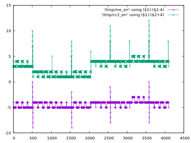
From: andrew cooke <andrew@...>
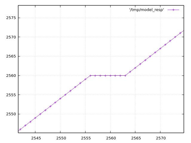
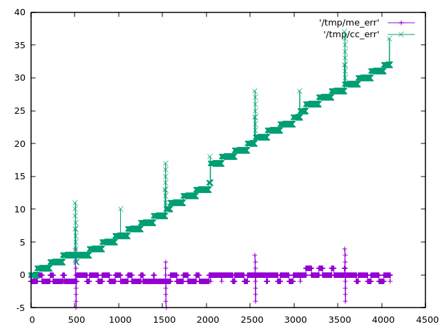
Date: Thu, 10 Jul 2025 20:02:51 -0400
The Raspberry Pico 2040 has a problem with the ADC.  It's described in
https://datasheets.raspberrypi.com/rp2040/rp2040-datasheet.pdf
(see section 4.9.4 and the worrying low ENOB just before).

The DNL and INL in that datasheet are explained at
https://www.allaboutcircuits.com/technical-articles/understanding-analog-to-digital-converter-differential-nonlinearity-dnl-error/

If I've understood correctly that means that there are a few places
where the ADC output "sticks" at a particular input value instead of
incrementing.  As the input continues to rise, after it has "missed" 8
or so bits, it "unsticks" and continues increasing from where it left
off.

In Python I've tried to create a simplified model of the ADC response
from the datasheet.  If that model is correct then
https://acooke.org/img/pico-model.png shows one of these places (input
analog voltage is the x axis; ADC output is the y axis).

Reading through the MTM ComputerCard.h code at
https://github.com/TomWhitwell/Workshop_Computer/blob/main/Demonstrations%2BHelloWorlds/PicoSDK/ComputerCard/ComputerCard.h
I noticed a fix for this (round line 527).

(I should say here that the ComputerCard.h library is awesome and has
taught me a huge amount about the pico - huge thanks to Chris
Johnson).

I'll copy the code here:

    // Attempted compensation of ADC DNL errors. Not really tested.
    uint16_t adc512=ADC_Buffer[cpuPhase][3]+512;
    if (!(adc512 % 0x01FF)) ADC_Buffer[cpuPhase][3] += 4;
    ADC_Buffer[cpuPhase][3] += (adc512>>10) << 3;

The correction has two important parts.  The first is

    if (!(adc512 % 0x01FF)) ADC_Buffer[cpuPhase][3] += 4;

which is targeting the spikes in the DNL plot in the datasheet (see
above).  This is an attempt to shift the "stuck" values into the
middle of the range, although I don't understand why the value 0x1FF
is used here - I think that would be the distance between the DNL
peaks, which appears to be 0x200.

The second, more significant part, is

    ADC_Buffer[cpuPhase][3] += (adc512>>10) << 3;

which is a really cool way of adding in the "zig-zag" offset that
appears in the data.  It's picking off the topmost bits of the ADC
value as needed.  If that's still not clear and you're curious, play
with my code below - plot the values when removed and it becomes
pretty clear.

Anyway, I started experimenting myself and found two more fixes.  One
corrects an offset of a few bits over part of the range, and the other
simply rescales back to the 0-4095 range (using the "standard" trick
of representing a fraction as an integer multiplication plus a shift /
division of a power of 2).

So "my" correction (the best part of which is taken directly from the
ComputerCard.h code above), in Python, is:

    def me_correcn(a):
        b = a + (((a + 0x200) >> 10) << 3)
        if (a & 0x600) and not (a & 0x800):
            b += 2
        if (a + 0x200) % 0x400 == 0:
            b -= 4
        return (520222 * b) >> 19

The expected errors of the two corrections are plotted in
https://acooke.org/img/pico-error.png and while "my" correction looks
nicer I am not sure if it works, yet, or is "worth it" in
terms of computational cost.

So I will push on and try to get some code working.  For now I am
simply putting this out there.

Andrew

PS There was a little extra background given by Chris in the MTM
Discord.  I haven't followed up there yet because I don't yet have
running code and I'm not so confident this is correct... (amongst
other things, I'm worried about an off-by-one error in my
implementation of DNL and INL)

PPS Almost forgot, here's my Python code (I use gnuplot for plots):

#!/usr/bin/python3

from os.path import exists
from os import remove
from functools import cache

# guessed from plot (within 0.25?)
# +ve values from DNL, -ve from INL
# -ve sample number inferred from pattern (might be ignoring step near 2048)
#DNL_OBS = {512: 9.0, 1536: 7.25, 2048: -3.0, 2560: 7.5, 3072: -1.0, 3584: 8.0}

# but for monotonic conversion DNL cannot be less than -1 so presumably it's more like
DNL_OBS = {512: 9.0, 1536: 7.25, 2047: -1.0, 2048: -1.0, 2049: -1.0, 2560: 7.5, 3072: -1.0, 3584: 8.0}
# (which might be visible in the DNL plot in the data sheet)
# (i'm also ignoring something at 511 in the DNL plot that may be an aliasing issue in the plot itself?)

# i find it easier to think of bin widths with expected value of 1 (these are non-negative)
WID_OBS = {k: v+1 for k, v in DNL_OBS.items()}

# assume others are equal in width and the total width is given
WID_OTHER = (4096 - sum(WID_OBS.values() )) / (4096 - len(DNL_OBS))

# i'm using indices from 0 which may be wrong?

# given an analog value, calculate the measured value by the dac
# from https://www.allaboutcircuits.com/technical-articles/understanding-analog-to-digital-converter-differential-nonlinearity-dnl-error/
# (esp figure 1 and the text below) index 1 corresponds to an output of 1
@cache
def model_resp(a):
    d = 0
    a -= WID_OTHER / 2  # if a is less than 1/2 a typical gap (or 1) then d is 0
    while a > 0:
        d += 1
        # move to next bin
        if d in WID_OBS:
            a -= WID_OBS[d]
        else:
            a -= WID_OTHER
    return d

# plot a function to a file
def plot(fn, path):
    if exists(path): remove(path)
    with open(path, 'w') as out:
        for x in range(4096):
            print(x, fn(x), file=out)
    print(f"output in {path}")

# given a response, calculate the error
def resp_to_err(resp, scale=1):
    if scale != 1: print('scale', scale)
    @cache
    def err(x):
        return resp(x) - x * scale
    return err

# the correction in ComputerCard.h
def cc_correcn(x):
    # uint16_t adc512=ADC_Buffer[cpuPhase][3]+512;
    adc512 = x + 512
    # if (!(adc512 % 0x01FF)) ADC_Buffer[cpuPhase][3] += 4;
    if (adc512 % 0x01ff) == 0: x += 4
    # ADC_Buffer[cpuPhase][3] += (adc512>>10) << 3;
    x += (adc512>>10) << 3
    return x

def apply(resp, correcn):
    def f(x):
        return correcn(resp(x))
    return f

plot(model_resp, "/tmp/model_resp")
model_err = resp_to_err(model_resp)
plot(model_err, "/tmp/model_err")

cc_corrected = apply(model_resp, cc_correcn)
plot(cc_corrected, "/tmp/cc_corrected")
cc_err = resp_to_err(cc_corrected)
plot(cc_err, "/tmp/cc_err")
cc_err_scl = resp_to_err(cc_corrected, scale=cc_corrected(4095)/4095)
plot(cc_err_scl, "/tmp/cc_err_scl")

k = 1 << 19

# errors (in model) at 512 1536 (2048) 2560 3584
# diffs 1024 1024 1024
# scale inside 32bit (value is about 12 bits)
def me_correcn(a):
    global k
    b = a + (((a + 0x200) >> 10) << 3)
#    if 512 < a < 2048:
    if (a & 0x600) and not (a & 0x800):
        b += 2
    if (a + 0x200) % 0x400 == 0:
        b -= 4
    return (k * b) >> 19

k = int(4095 * (1 << 19) / me_correcn(4095))
print(k)  # 520222

me_corrected = apply(model_resp, me_correcn)
plot(me_corrected, "/tmp/me_corrected")
me_err = resp_to_err(me_corrected)
plot(me_err, "/tmp/me_err")
From: andrew cooke <andrew@...>
Date: Tue, 1 Jul 2025 15:27:44 -0400
I am writing some (audio) synthesis code for a CPU without fast
division.  Internally, amplitude is described with int16_t, but for
some processes (eg wavefolding) it's useful to switch to floats.
Without fast division this switch could be expensive.  So I started to
prematurely optimize...

I realised that one way to convert between the two was to directly
write to the mantissa part of an IEEE float - the float then
"automatically" has the correct value without any explicit conversion.
The only tricky technical details seemed to be handling the hidden bit
and getting the exponent correct (avoiding denormalized values).

But I ended up spending too much time on the details of type punning
(that C trick of writing and reading from a union using different
types).

First, it turns out that type punning is not supported in C++, but
seems to work in g++ (and C++23 has start_lifetime_as which can, I think,
be trivially used to replace the type punning in my final code below).

Second, the code at https://stackoverflow.com/a/15685301 DOES NOT
WORK.  Maybe it works in C - I don't know, I haven't tried it.  But in
C++ it fails.  The reason is described at
https://en.cppreference.com/w/cpp/language/bit_field.html - second
example, with the comment "6 bits for b2 - doesn't fit into the 1st
byte => starts a 2nd".

(If you have no idea what I'm talking about
https://en.wikipedia.org/wiki/IEEE_754 might help).

So you end up having a union of a float with an uint32_t and doing the
separation into the different components manually.  And that does
work!  Although I still have no idea if it's faster that division.

Here's the code.

header:

  class IEEEFloat {

  public:

    IEEEFloat(double f);
    IEEEFloat(float f);
    IEEEFloat(int v);
    IEEEFloat(int16_t v);
    IEEEFloat(uint32_t m, uint32_t e, uint32_t s);

    float f();
    uint32_t m();
    uint32_t e();
    uint32_t s();
    int16_t sample();
    void dump(std::ostream& c);

  private:

    const uint32_t hidden = 1 << 23;
    const uint32_t mask = hidden - 1;

    typedef union {
      float f;
      uint32_t u;
    } float_cast;

    float_cast fc;

  };


  float sample2float(int16_t s);

  int16_t float2sample(float f);


and implementation:

IEEEFloat::IEEEFloat(double v) : IEEEFloat(static_cast<float>(v)) {};

IEEEFloat::IEEEFloat(float v) : fc({.f=v}) {};

IEEEFloat::IEEEFloat(uint32_t m, uint32_t e, uint32_t s) : fc({.u=0}) {
  fc.u = ((s & 1) << 31) | (e & 255) << 23 | (m & mask);
}

IEEEFloat::IEEEFloat(int v) : IEEEFloat(static_cast<int16_t>(v)) {};

IEEEFloat::IEEEFloat(int16_t v) : fc({.u=0}) {
  if (v != 0) {
    uint32_t s = static_cast<uint32_t>(v < 0) << 31;
    uint32_t e = 127;
    uint32_t m = static_cast<uint32_t>(abs(v)) << 8;
    while (! (m & hidden)) {
      m = m << 1;
      e--;
    }
    fc.u = s | (e << 23) | (m & mask);
  }
}

float IEEEFloat::f() {
  return fc.f;
}

uint32_t IEEEFloat::s() {
  return (fc.u >> 31) & 1;
}

uint32_t IEEEFloat::e() {
  return (fc.u >> 23) & 255;
}

uint32_t IEEEFloat::m() {
  return fc.u & mask;
}

int16_t IEEEFloat::sample() {
  if (e()) {
    int16_t v = static_cast<int16_t>((m() | hidden) >> (8 + 127 - e()));
    if (s()) v = -v;
    return v;
  } else {
    return 0;
  }
}

void IEEEFloat::dump(std::ostream& c) {
  c << fc.f << " (" << std::hex << m() << ", " << std::dec << e() << ", " << s() << ")" << std::endl;
}


float sample2float(int16_t s) {
  return IEEEFloat(s).f();
}

int16_t float2sample(float f) {
  return IEEEFloat(std::max(-0.999969f, std::min(0.999969f, f))).sample();
}


TEST_CASE("IEEEFloat") {
  CHECK(sample2float(sample_max) == doctest::Approx(1).epsilon(0.001));
  CHECK(sample2float(sample_max/2) == doctest::Approx(0.5).epsilon(0.001));
  CHECK(sample2float(0) == doctest::Approx(0).epsilon(0.001));
  CHECK(sample2float(sample_min/2) == doctest::Approx(-0.5).epsilon(0.001));
  CHECK(sample2float(sample_min) == doctest::Approx(-1).epsilon(0.001));
  CHECK(float2sample(1.0) == doctest::Approx(sample_max).epsilon(0.001));
  CHECK(float2sample(0.5) == doctest::Approx(sample_max/2).epsilon(0.001));
  CHECK(float2sample(0.0) == doctest::Approx(0).epsilon(0.001));
  CHECK(float2sample(-0.5) == doctest::Approx(sample_min/2).epsilon(0.001));
  CHECK(float2sample(-1.0) == doctest::Approx(sample_min).epsilon(0.001));
  for (int32_t s = sample_min; s <= sample_max; s += 1234) {
    CHECK(float2sample(sample2float(s)) == doctest::Approx(s).epsilon(0.001));
  }
  for (float f = -1; f <= 1; f += 0.123) {
    CHECK(sample2float(float2sample(f)) == doctest::Approx(f).epsilon(0.001));
  }
}


where sample_max and sample_min are 32767 and -32767 respectively.

Andrew
From: andrew cooke <andrew@...>
Date: Thu, 26 Jun 2025 18:11:21 -0400
I've just got "hello world" working on the Music Thing Modular (MTM).
Here are a few notes:

- I didn't really follow anyone's instructions or project layout,
  which in retrospect would have made things simpler.

- Instead, I started writing the code I wanted to deploy long before I
  got the machine.  I wrote in emacs and called g++ via a shell script
  to compile.  This worked fine for developing my small project, but I
  just saw CLion is free for non-commercial use, so will probably
  switch to that at some point.

- When I had the machine I realised I needed to do a fair amount of
  work making it "uploadable": I needed to move to CMake, integrate
  with the RPi pico SDK, and get cross-compilation working.

- I run Fedora on my laptop and a quick google suggested
  cross-compiling on that wasn't great.  So I installed Debian testing
  on a VM (Debian is the basis of the RPi linux and seems to have lots
  of support).  What follows is therefore for Debian.

- I moved my project to CMake, which meant splitting into src and
  include directories, and adding the following CMakeLists.txt:

    $ cat CMakeLists.txt

    cmake_minimum_required(VERSION 3.13)

    #set(PICO_BOARD mtm_computer_16mb CACHE STRING "Board type")
    set(PICO_SDK_FETCH_FROM_GIT on)
    include(pico_sdk_import.cmake)

    project(
      cosas
      VERSION 0.0
      DESCRIPTION "just trying to get cmake working"
      LANGUAGES CXX C)   # C for sdk - https://stackoverflow.com/a/74591212

    include(FetchContent)
    FetchContent_Declare(workshop-computer
			 GIT_REPOSITORY https://github.com/TomWhitwell/Workshop_Computer.git
			 GIT_TAG        main)
    FetchContent_MakeAvailable(workshop-computer)

    pico_sdk_init()
    add_subdirectory(src)
    set(CMAKE_EXPORT_COMPILE_COMMANDS ON)
    set(CMAKE_CXX_EXTENSIONS OFF)
    set(DOCTEST_CONFIG_DISABLE ON)
    add_executable(cosas hello-world.cpp)
    target_compile_features(cosas PRIVATE cxx_std_20)
    target_compile_definitions(cosas PRIVATE DOCTEST_CONFIG_DISABLE)
    target_link_libraries(cosas PRIVATE cosas_lib pico_stdlib)
    pico_add_extra_outputs(cosas)   # generate uf2
    pico_enable_stdio_usb(cosas 1)  # allow serial over usb

  (Note that this includes some stuff I am unsure about, like the
  WorkshopComputer repo - I assume I will need that later).

- Given that, in the same directory this creates the environment:

    $ cat install.sh
    #!/bin/bash

    cd "$(dirname "${BASH_SOURCE[0]}")"

    sudo apt install cmake gcc-arm-none-eabi libnewlib-arm-none-eabi libstdc++-arm-none-eabi-newlib g++

    if [ ! -e pico_sdk_import.cmake ]; then
	wget -L https://raw.github.com/raspberrypi/pico-sdk/master/external/pico_sdk_import.cmake
    fi

    mkdir -p build
    pushd build > /dev/null
    cmake ..

- And then "cd build; cmake --build" builds the code.

- This small hello world program doesn't actually use anything I've
  written but ddoes test that deploy works:

    $ cat hello-world.cpp

    #include <stdio.h>
    #include "pico/stdlib.h"

    int main() {
	stdio_init_all();
	while (true) {
	    printf("Hello, world!\n");
	    sleep_ms(1000);
	}
	return 0;
    }

- Running cmake (above) creates a uf2 file that I can upload tp the
  MTM by following the instructions on their site (basically hold the
  hiddent button down, tap the normal button, and then copy the uf2
  file to the upload diretcory.

- Restarting everything, "cat /dev/ttyACM0" shows the hello world
  message.

There are lots of details missing (feel free to ask, although I have a
memory like a sieve) - this is more to say that it is possible and to
encourage others.

Now I need to actually deploy the code I have...

Andrew
From: andrew cooke <andrew@...>
Date: Thu, 10 Apr 2025 19:36:05 -0400
i bought a cycling mirror (the "take a look" compact model that is
sold on amazon) and tried it today.  here are my first impressions (i
am trying to order them from specific to general):

- it's very well made for something so light and seemingly delicate.
  the mount on my glasses was secure, the adjustments easy, nothing
  moved out of adjustment (even on a road bike on santiago's bumpy
  roads), the mirror was clear and undistorted, and - most impressive
  of all - it was absolutely solid.  no wobbling or shaking.

- i use prescription glasses - i cycle in the same glasses i use all
  day.  the mirror mounted on the left arm (here we ride on the right)
  and takes up the top left corner of the glasses frame that i see
  when i look out of left eye.  in other words, it couldn't be higher
  or further outboard without being blocked by the frame or out of
  focus (i am short sighted).

- when i cycle there's not a single position (angle) that i hold my
  head at.  when i am more tired, or going faster, my head is lower.
  when paying attention to my environment, or climbing, my head is
  higher.  this means that there is not one "perfect" adjustment for
  the mirror (which is flat, not convex): i needed to choose the head
  position (angle) at which i would adjust the mirror for the best
  view.

- even at this optimum position i cannot see directly behind me.  my
  cheek/shoulder is in the way.  to see directly behind me i need to
  move my head slightly (look slightly to the left).

- and even with my head turned, i cannot see the road if it curves
  away to my right (conversely, if the road curves away to the left i
  don't need to turn my head).  so on winding (mountain) roads it is
  useful maybe 2/3 of the time.

- the mirror is only visible in my left eye (obviously).  sometimes
  that doesn't seem to matter - my brain switches to using just that
  eye if i want to look behind me - but sometimes it does, and it is
  hard to focus / understand without closing the right eye.  this
  seems to depend to some extent on the ambient lighting.

- the mirror blocks my left eye from looking in that direction (again,
  obviously).  this can be important at junctions since it makes it
  harder to see traffic coming from the left.  sometimes my brain
  switches to the right eye and there's no real issue, but sometimes
  it doesn't.  again, it seems to be lighting dependent.

- (if you have visual migraines) the mirror feels annoying like a
  visual migraine, in that there's something in your field of view
  that seems "wrong".  after a three hour ride i was starting to feel
  the hint of a headache from this.

- i suspect the three issues immediately above will all improve with
  practice.

- perhaps because of the need to angle my head i didn't feel like the
  mirror was an improvement over my ears.  in fact, my ears are
  better, in that they can hear cars round corners.  and one of the
  things i learnt was that my ears are pretty damn accurate - i would
  hear something, look in the mirror to check, and get confirmation of
  vehicle type and position / distance.

- on the other hand, on descents, or with headwind, when there's a lot
  of wind noise in my ears, the mirror did feel more useful.  in that
  sense it complements, rather than replacing, hearing.

- the moments when i was surprised by something in the mirror were
  when vehicles i had not heard or seen started to pass me.  they
  appeared in the mirror just before they appear in peripheral vision
  (this did not seem to be particularly useful information).

- it was kinda cool to see cars drop away behind me when descending
  quickly.

- i was self-conscious about using the mirror, but in practice i don't
  think anyone much noticed.  it reminded me of how i felt (many years
  ago) when i first used lycra - very self-concious, but noone else
  cared.  also, despite what i've seen in some online images, the back
  of the mirror is a neutral grey.

- i still look behind me before doing anything particularly risky.
  the mirror doesn't really replace that.  maybe it would with more
  practice?

- my overall reaction to the mirror is simiar to how i expect i'd feel
  about varia: it provides a little extra info, but it's not really
  useful / actionable.  and they're both kinda nerdy.

- the one place i can think of where the mirror might be critical is a
  fast right fork (where i ride straight on / left).  after a near
  miss there last week i am considering simply stopping until things
  are clear.  i will ride there on my next ride - maybe the mirror
  will mean stopping is not necessary?

- the main conclusion from all this - for me - was that, above all, i
  *really* rely on car drivers not killing me.  i don't see a way round
  this - the mirror doesn't change things much.

- my second conclusion is that i should get some of those "cat ears"
  to reduce wind noise, given how useful my ears are.  and i bet they
  are less geeky to wear (they don't *look* like cat ears...)

andrew
From: andrew cooke <andrew@...>
Date: Fri, 21 Feb 2025 16:03:31 -0300
Loved this and wanted to record it here in case it's deleted later.
Also, I need to sort out this place and get rid of all the spam, I
know.

https://www.reddit.com/r/Professors/comments/1iuqq6y/what_is_the_line_between_paranoia_and_preparedness/me0ejh0/

Credit to DerProfessor https://www.reddit.com/user/DerProfessor


[In response to an acacdemic worrying about the future]

Honestly, I would say--don't worry about it. I myself am not going to
adjust anything one single iota. In part, because staying the same is,
effectively, resistance.

I am a historian of Germany, including of the Third Reich (though it's
not my specific area of research). I know a great deal about how the
Nazis solidified power 1933-1934. This is not that moment.

One thing that has been consistent about Trump is that he bluffs on
everything. Everything. This has been his standard mode-of-operation
his whole life, from being a real-estate conman to posing as a fascist
strongman. His posing and bluffing has gotten him what he wants a lot
of the time. But equally, it is often hot air when he is ignored.

The key word here is posing. Neither he nor the Republicans have
mechanical structures (police, informants, allies in the academy, mass
movement) to ever "see" what you are doing, let alone impact you as an
individual professor.

Consider: what levers does he have? When you say "when they will come
for us"... who is they? And how will "they" even know who you are?

Let us imagine that, over the next two years, an office is set up
somewhere, to collect syllabi and thereby try to police teaching. How
would the office be set up? (especially when the Dept of Education is
being dismantled?) Who would be hired to work there? How would they
"demand" the syllabi? If your university already posts them publicly,
how would they collect them? There are millions of classes
taught. They'd need to hire thousands just to read the ones that AI
flags for words like "race". Then, what would be the mechanism for
enforcement? Would this department call up your local police
department and say, "We see that Professor Fit_Inside2339 at the
University of Innuendo is teaching a class on race and ethnic
relations... we need you to go arrest him." Any police officer, even a
dyed-in-the-wool Trumpy, would laugh in their face.

You're safe. You're fine.

The Nazis could terrorize professors because 40% of professors were
themselves Nazi supporters. That is crucial. Do you have a single
colleague who is a Trump supporter? Even one? (The redneck dumbasses
in their lifted trucks don't even know where the university is, let
alone your classroom.)

The Nazis also had the Gestapo. But recent literature reveals how
incredibly ineffectual the Gestapo was on its own. They relied
entirely on denunciations, they were reactive only. Who would denounce
you? We ALL hate that orange motherfucker. No one is going to go
running to denounce you as Unamerican... and even if you got a
politicized student in your class who wanted to, who would this
self-destructive student denounce you to? There's no infrastructure of
oppression.

Trump has no Gestapo. He has no control over police. He has no
supporters in the academy. MOST importantly, he has no mass
movement. (He has a bunch of passive, flag-waving supporters. that's
different. that's just normal politics.)

The one area that he does have control over is ICE/immigration
structures, which already exist, and are already staffed with people
predisposed to obey Trump's orders, legal or not. So, people who are
undocumented are, indeed, facing a serious personal threat. Those
folks are in trouble (and they therefore need our help and
protection). But you're fine.

Trump's "power" vis-a-vis academia is twofold: 1) to bluster loud
enough, and play-act the fascist enough, so that people (like you and
me) comply preemptively. THAT's not gonna happen. (unless you let it.)

And 2) to disrupt money flowing to Universities, to try to pressure
your Provost/Dean etc. into become stooges to force faculty to
comply. Honestly, I don't think that's going to happen either. Sure,
maybe a particularly craven Dean will come to your department and say,
"look, I support you, but you need to retitle your classes so we can
get our NIH grants back." And yes, that will be "complying". I
honestly hope that doesn't happen. But if it does... so what? You
retitle "Race in American Politics" to "Varieties of Identities in
American Politics"... teach the same course... and then savagely mock
that cowardly dean behind his back. (and remember his cowardice in the
future.)

There will be some rough times, don't get me wrong. For instance,
there will be NO more Federal grants for your type of research for the
foreseeable future. But your teaching? You'll be fine. I'll be fine.

And the more we just keep doing what we've been doing all along, the
"finer" we ALL will be!

In solidarity.
From: andrew cooke <andrew@...>
Date: Thu, 25 Jan 2024 16:43:27 -0300
https://en.wikipedia.org/wiki/Unexpected_hanging_paradox describes a
paradox I've heard various times that has always frustrated me.

A discussion somewhere (reddit?) pointed to
https://www.ams.org/notices/201011/rtx101101454p.pdf which is really
interesting - in short their argument is that it assumes consistency
in the theory in which it is dervied, coming up against Godel's second
theorem.

Andrew